Gear Purchasing Guide

Looking for a durable, reliable and affordable belt?
_cropped_250_280.webp)
WHY CHOOSEA GEAR?
What is a gear?
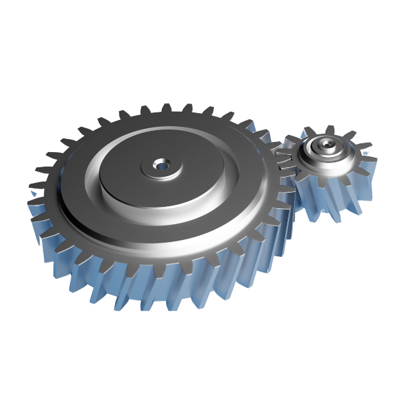
A gear is a mechanism made up of two interlocking toothed wheels, enabling the transmission of motion or power at a constant speed ratio.
It consists of at least two interlocking gearwheels, which vary torque and speed to transmit rotary motion. Rotation of the first gear drives the second through interference between their teeth.
When a gear consists of more than two wheels, it is referred to as a gear train. Its main purpose is to modify rotational speed and torque, these two quantities being inversely proportional.
The role of a gear
Gears serve two main purposes: speed acceleration or force enhancement. However, achieving one of these objectives often requires compromises.
For example, to increase the speed of a bicycle's wheels, you need to increase the force exerted on the pedals. Similarly, to increase the force applied to the wheels, you need to turn the pedals faster. This strategy is put into practice when cyclists face steep climbs. These principles are closely linked to the laws of conservation of energy and power.
Gears are used in all branches of mechanics requiring the transmission of motion: without these mechanisms, there would be no car engine, or even no assembly line.
It's the combination of different gear formats that enables you to achieve the desired objective: a system made up of two wheels will necessarily have a drive wheel. It's this gear that transmits motion to your gear line and dictates movement to the rest of the driven wheels.
How a gear works
When a driving gear turns, it drives the other gear it's in contact with. The relationship between the speed of rotation of the two gears is determined by the ratio of their number of teeth. For example, if a small gear drives a large gear, the speed of rotation will be reduced, but the torque will be increased. Conversely, if a large gear drives a small gear, speed will be increased while torque will be reduced.
Two gears can only mesh together if they have the same module.
There is no such thing as a gear with just any module. Modules are standardized: Some examples of standardized modules

GEARADVANTAGESAND LIMITATIONS

Benefits
- The gears are mechanically strong, enabling them to lift higher loads.
- Thanks to a gearbox, they enable gear ratios to be changed, offering adaptability in different situations.
- Efficient low-speed operation
- Gears transmit power with high efficiency.
- They need only routine lubrication, so require little maintenance attention.
- Their outstanding durability guarantees reliable operation over the long term


LIMITS
- Gears are not flexible in use, limiting their adaptability.
- They are not suitable for transmitting motion over long distances.
- At high speeds, gears can be noisy,
- When shafts are far apart, gears may not be the best option
- Gears may require regular maintenance and frequent lubrication
- If poorly designed or misaligned, gears can be prone to premature wear or failure, requiring costly repairs.
GEARTYPES
Their design varies according to the specific needs of each application, and among the most commonly used types are single-tooth gears, helical gears and bevel gears. Each of these types has unique characteristics and offers distinct advantages in terms of performance and applications.

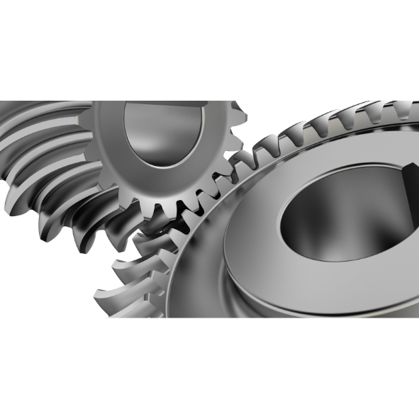
Spur gears

Bevel gears

Helical gears
FACTORSTO TAKE INTO ACCOUNT WHEN CHOOSING A GEARBOX
Environment : the durability and performance of a gear depends on two important factors - operating conditions and environmental conditions. Operating conditions include the stresses and friction exerted on the teeth. On the other hand, environmental conditions include humidity, temperature and cleanliness. Both conditions affect gear type and design factors such as construction, surface treatment, lubricants and lubrication method.
Dimensions : Consideration of the space gears occupy is crucial. Although they are usually centered between shafts, it may be necessary to make adjustments to adapt them to the gear system. In such circumstances, tooth profiles can be modified. To manage these limitations effectively, it is essential to opt for specific equipment and designs that best match the available space.
Transmission requirements : When designing gears, it is important to take into account the specifications and requirements of the application, such as changes in direction or speed or torque amplification. These factors can influence the choice of gear type, design and configuration.
Standards : Often, gear designs conform to the manufacturer's standard or the design specifications of the machine or system. However, many countries have created a standard to serve their industries. For example, in the USA, gears are grouped under the American Gear Manufacturers Association (AGMA). Japan and Germany also have such associations.
Cost : Design materials, construction, surface finishes, precision and lubrication requirements affect costs. While it is necessary to use gears that meet all specifications, cost must be taken into account. So, where regular gears meet standards, it's best to use them, as custom gears will incur further expense.
GEARMACHINING
Gear machining is an essential process in the manufacture of these crucial mechanical components. It involves shaping gear teeth and profiles from raw materials, using a variety of techniques and specialized machine tools. The main gear machining methods include gear milling, gear hobbing, gear grinding, gear hobbing and forging.

Tooth milling : This method involves using a specially designed cutter to carve gear teeth out of a raw material, usually metal.
Gear hobbing : In this technique, a hob or cutter is used to shape the gear teeth directly into the raw material without the need for an additional milling operation.
Gear grinding : Grinding is used to obtain very precise tolerances and an optimum surface finish on the gear teeth. This involves the use of an abrasive wheel to shape the teeth to the required dimensions.
Generative hobbing : This method uses special tools, such as generation hob cutters, to shape the gear teeth to the profile of the generator. This results in high precision and good surface quality.
Forging : In some applications, gears can be manufactured by forging them from metal blanks. This method is often used to produce large, high-strength gears.
MECHANICAL GEAR ASSEMBLIES
 |
 |
 |
 |
 |
|
| Gear types | Gears cylindrical |
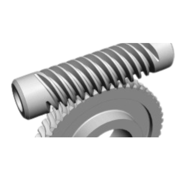
Helical gears | Bevel gears | Reducer wheel and worm |
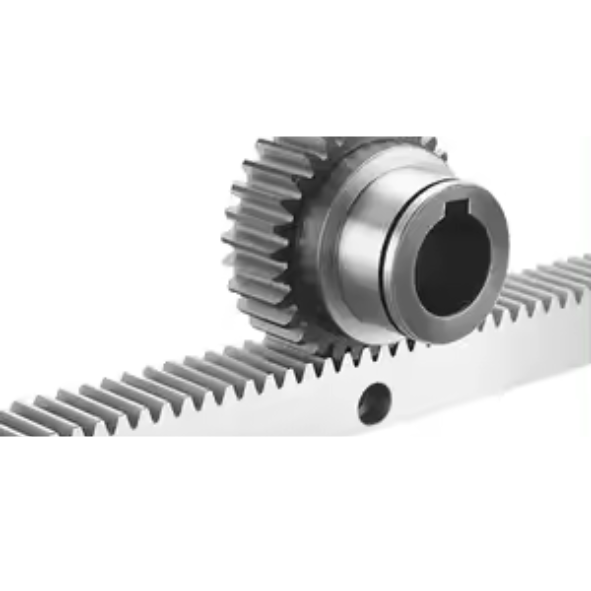
Rack and pinion |
| Features |
|
|
|
|
|
| Applications |
|
|
|
|
|
GEARGLOSSARY
Module
Thanks to its internal structure X-shaped raceways with a contact angle of 50% (unique on the market), the linear guide will accept and compensate for imperfections in the support for optimum operation.
Pressure angle
Rolling elements connecting the mobile shoe to the fixed rail. In the NH-NS series, the rolling elements are precision balls (various classes).
Toothed wheel
Toothed organ designed to move another, or to be moved by the action of successively contacting teeth
Axis angle
The smallest angle by which one of the axes must be rotated to bring it into superimposition (concourant gearing) or parallelism (left-hand gearing) with the other, so that the directions of rotation of the wheels are opposite.
Planetary train
The epicyclic gear train is a power transmission system made up of three main components: a ring gear, a sun gear and one or more satellites. These are arranged in such a way as to create a complex rotational movement that transmits power from an engine to the car's gearbox.
Planetary train
The epicyclic gear train is a power transmission system made up of three main components: a ring gear, a sun gear and one or more satellites. These are arranged in such a way as to create a complex rotational movement that transmits power from an engine to the car's gearbox.
Multiplying gear
Multiplying gear train
gear or gear train where the angular speed of the last driven wheel is greater than that of the first driving wheel
Primary operating area
Geometric surface described by the instantaneous axis of relative motion of the mating gear with respect to the gear under consideration, in a given gear
Note 1 to article: The primitive operating surfaces of parallel or concurrent gears roll without sliding over each other. Those of left-hand gears (cylindrical and hypoid) slide on each other along their flank lines.
Not
Distance between homologous profiles of two consecutive teeth measured according to a defined procedure
External gear
A wheel whose toothing has its head surface outside its root surface
Internal gear
A wheel whose toothing has its head surface outside its root surface
Primitive diameter
Gear base diameter, defined by the imaginary circle from which the teeth are formed.
Outside diameter
Diameter measured on the outside of gear teeth.
Foot diameter
Diameter at the base of a gear's teeth.
Circular pitch
Angular distance between two identical consecutive points on the pitch circumference of the gear.
Circular pitch
Angle formed by the tangent to the pitch circumference and the normal to the tooth surface.
Propeller
Angle or inclination of the teeth of a helical gear relative to the axis of rotation.
Game
Gap between the teeth of gears in contact.
Gear offset
the way in which the teeth of a gear are positioned in relation to the gear's axis of rotation. It is also known as "gear eccentricity"
External gearing
Gear where the teeth are formed outside the base circle.
Safety coefficient
Factor applied to the torque or working load of a gear to ensure reliable life and operation, taking into account load variations and operating conditions.
Safety coefficient
Factor applied to the torque or working load of a gear to ensure reliable life and operation, taking into account load variations and operating conditions.
Tooth flank
The inclined lateral surface of a gear tooth that is in contact with the tooth of another gear.
Fine-toothed gears
A gear with a relatively small module, designed for an application requiring high-speed or low-torque power transmission.
Tooth depth
The radial distance between the top of the tooth and the base of the teeth.
Tooth depth
An alternative measure of gear tooth size, expressed in millimeters, calculated by dividing the pitch diameter by the number of teeth.
FAQ
Here are some of the most frequently asked questions about gears!
What are the differences between gears and pinions?
one. Gears and pinions are similar, both mechanical devices containing teeth that facilitate power transmission. However, here are some key differences between the two.
b. Gear teeth fit together, while rockets lock together with a bicycle chain or military tank tracks.
c. Gears can transmit torque in parallel, perpendicular and other configurations, whereas rockets operate only along a parallel axis.
d. Gears are better suited to transmission over short distances, while sprockets and chains work well over longer distances.
e. Gears transmit torque in opposite directions. However, the opposite is the case with sprockets.
Which gears are best?
Different gear types are best suited to different functions, depending on specification requirements and needs. However, spur gears remain the most widely used gears. They achieve high precision and are relatively easy to manufacture.
What does the gear profile offset refer to?
The profile offset design meets two specific requirements for gears:
Enhancing gear robustness:
Thinning the tooth root reduces gear strength, especially when the number of teeth is reduced, as in the case of a spur gear with an offset coefficient of 0. For example, if the number of teeth is less than 17, the tooth root will be hollowed out. On the other hand, the introduction of a positive offset coefficient increases the thickness of the root, thus reinforcing the strength of the gear.
Adjusting center spacing :
When the sum of the profile offsets of the active and passive gear sets is positive, the center-to-center spacing can be increased. Negative values, on the other hand, decrease center spacing. This mechanism is often used to adjust the distance between the centers of helical gear sets. In particular, for gear sets where the distance between centers is not an integer, profile shifting can be used to adjust this distance so that it becomes one. However, it is important to note that increasing the positive profile offset may increase resistance, but beyond a certain value, it may excessively sharpen the tooth tip. Similarly, too much negative profile offset can lead to tooth root hollowing.
What is peak play?
Different gear types are best suited to different functions, depending on specification requirements and needs. However, spur gears remain the most widely used gears. They achieve high precision and are relatively easy to manufacture.
How to maintain gears
Gears require regular maintenance, including lubrication to reduce friction and wear, inspection for signs of damage or misalignment, and occasional replacement of worn parts.
What materials are gears made from?
There are different types of materials for gear production, both metals and non-metals. These materials include steel, cast iron, nylon, fiber, plastic, etc. The material to be used typically depends on the requirements of the gears.
What processing techniques are used for gears?
Before using ratios, certain processing techniques are generally applied. Typical are grinding, a type of surface finish common with CNC materials, and heat treatment. The surface finish of grinding is aimed at the smoothness and calmness of gear operations, while various heat techniques are used to impact the strength and durability of the gear.